Soft Robotic Fish and Artificial Muscle
Graduate research at the Xi Chen Lab, Columbia University, on fast-swimming soft robotic fish driven by a pre-stressed bi-stable "hair-clip" mechanism. Published as a co-authored preprint (arXiv:2206.14867).
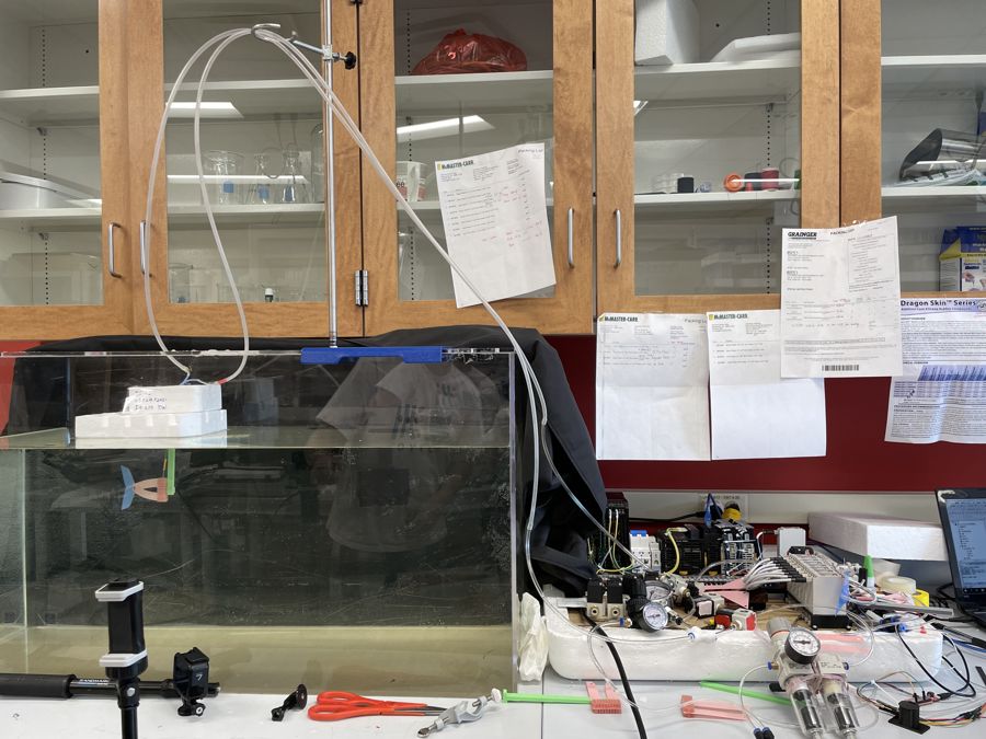
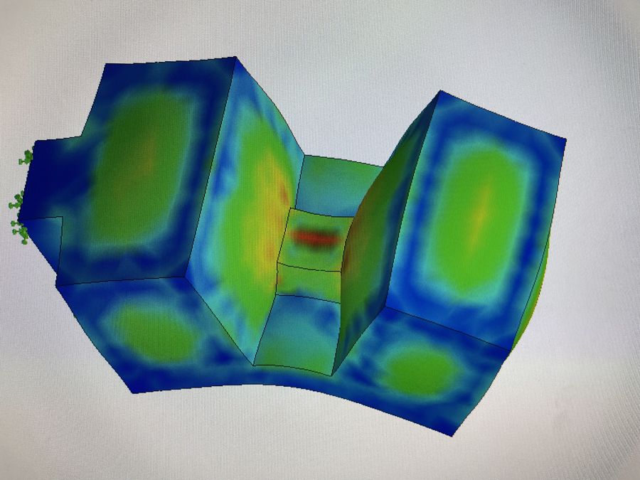
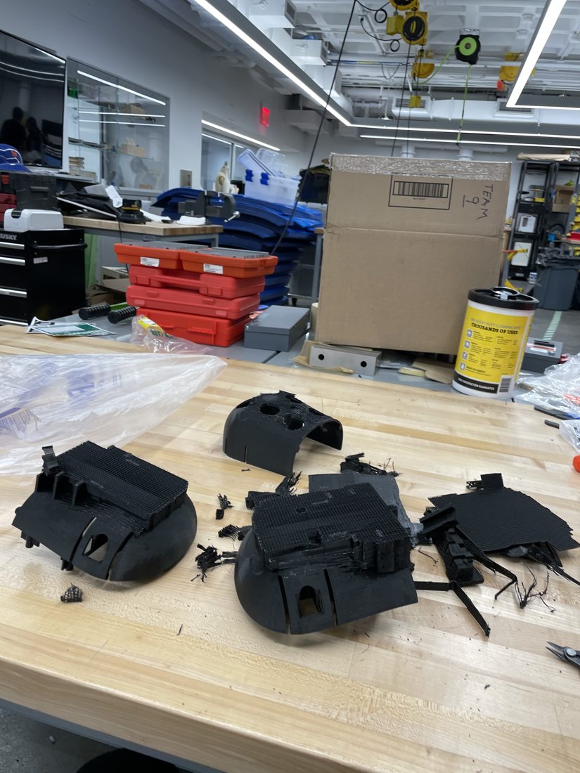
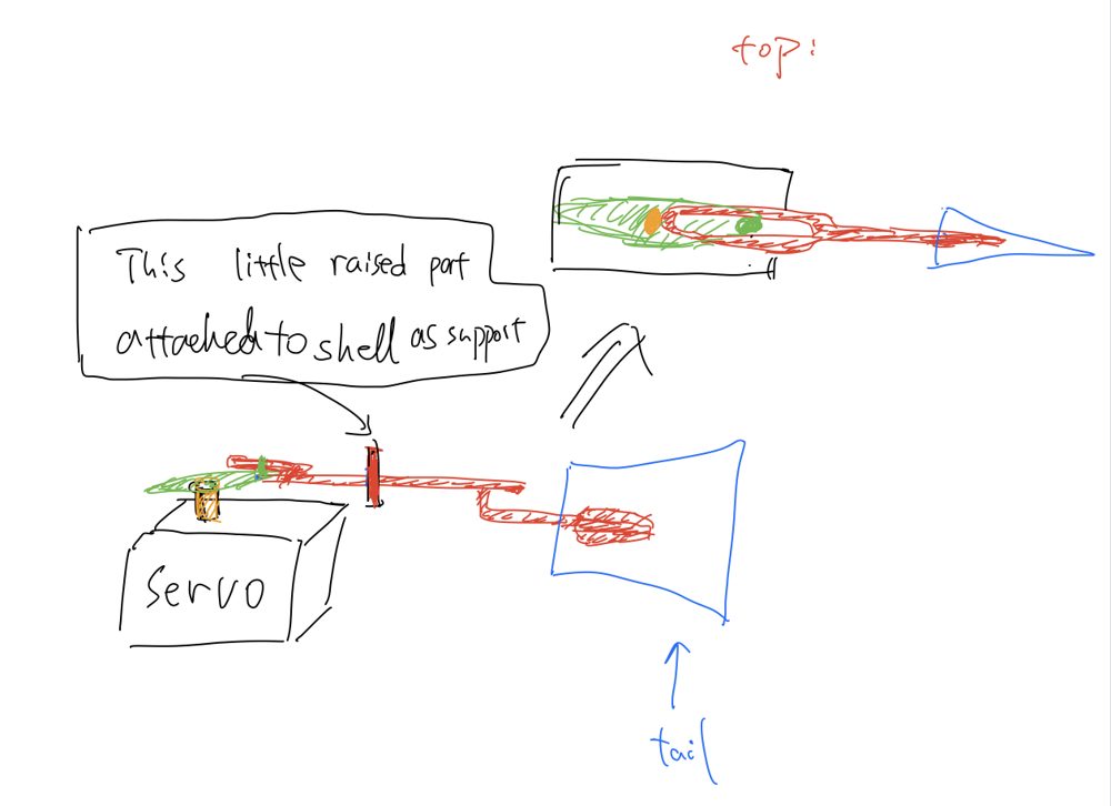
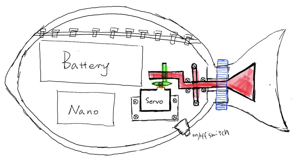
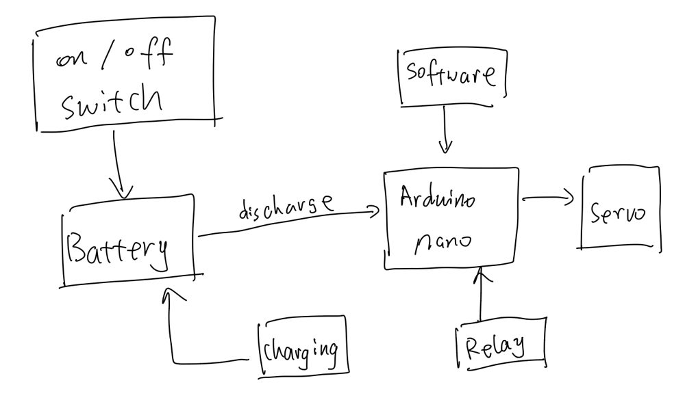
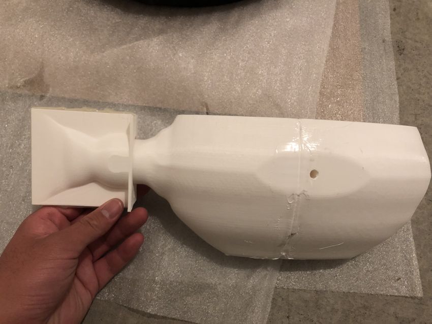
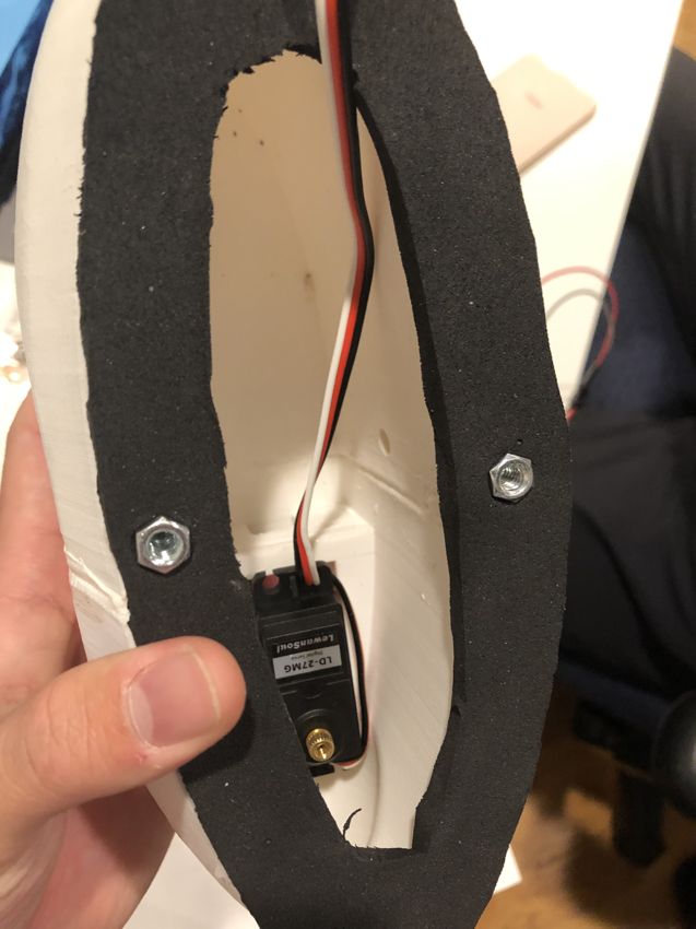
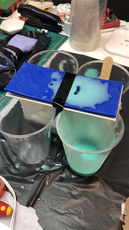
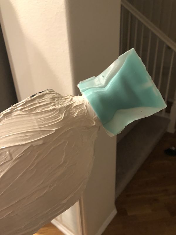
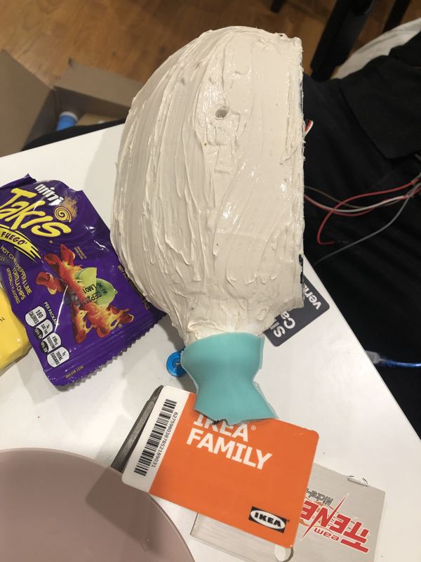
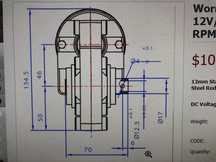
My work centered on the actuation. I built and compared two designs — a pneumatic-only fish and a pneumatic/SMA (shape-memory-alloy) hybrid — to find which made the fish swim fastest, prototyping each (CAD, 3D printing, silicone molding) and running them on a custom pneumatic test bench (solenoid-valve manifold, regulators, DC supply). The silicone actuators ballooned and leaked at higher pressures and faster actuation, so I used FEA to locate the high-stress regions behind that failure and fed the results back into the mold geometry to reinforce them. The pneumatic-only drive came out ahead.
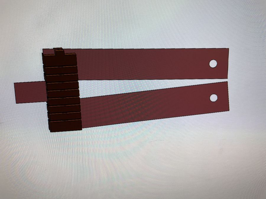
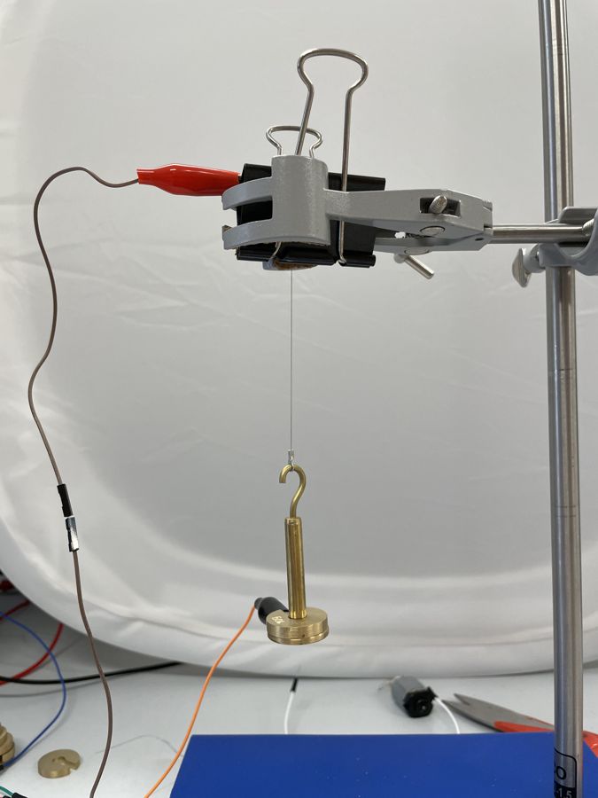
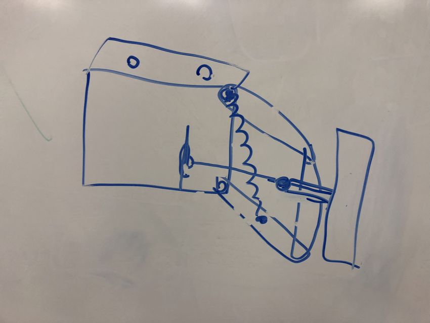
I also ran a characterization study on the bi-stable mechanism itself, laser-cutting and testing it across a range of materials and dimensions. Those results helped establish that its swing amplitude is scale-independent — one of the paper's key findings.
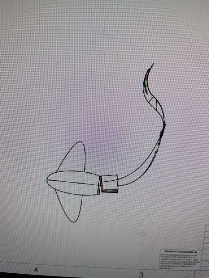
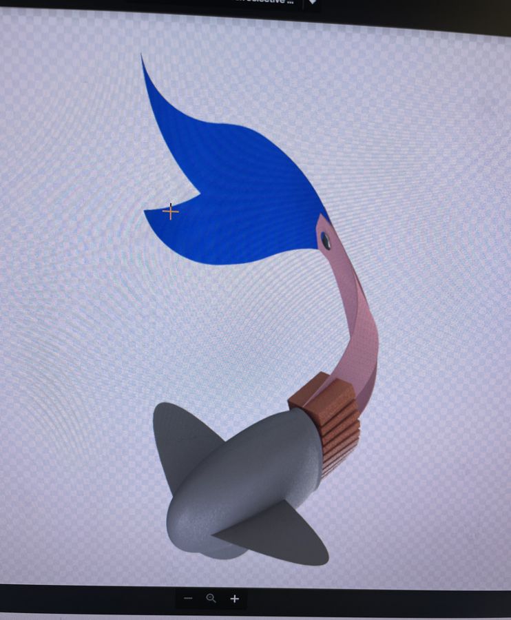
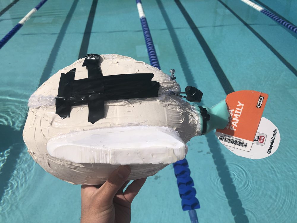
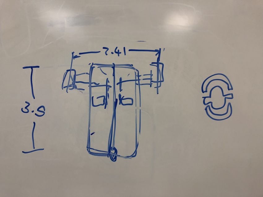
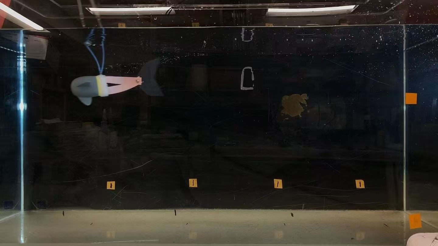
My other main contribution was the body design. I reworked it with internal cavities to set the fish's buoyancy and center of gravity so it tracked in a straight line, removing the external foam float earlier prototypes had relied on. That was the change that unlocked the speed: the pneumatic fish reached 1.40 body-lengths per second, a 2× improvement.